Why I used my vacation to write a Java assembler

As I usually do around this time of year, I took a much-needed one-week vacation from work at the beginning of May. With my recent scaling-back of the rosco_m68k project that’s been getting all my free time for the past couple of years, I needed a fun project to do during my time off, and I ideally wanted to take a break from Motorola 68k assembly and electronics and do something different.

Note: This is a pretty long post - if you don't feel like reading this wall of text and instead just want to see the code and some examples, check the project out on Github.

With that in mind, I decided I wanted to write a modern assembler for the JVM! I’ve been quietly maintaining this version of Jasmin for the past couple of years (though I’ve not really done much other than respond to an issue) via my involvement in the Code Shelter project, and while Jasmin is a venerable project with good usage, it’s getting quite long in the tooth now, and adding support for modern JVM features is tricky at best.

With that in mind, and week of free time stretching out in front of me, I decided I was going to see how far I could get with a brand-new assembler. My initial goals were:

  • Use ANTLR4 for lexing and parsing
  • User ASM 9.x for class generation
  • Support all JVM instructions (including INVOKEDYNAMIC) and modern features (such as dynamic constant pool entries)
  • Have a nice syntax (Jasmin’s .class syntax for example always bugged me slightly)

I specifically wanted to use ANTLR4 as I haven’t had chance to really play with it, but I had a lot of fun with v3 a while ago and felt like updating my skills. I also wanted to refresh my skills with ASM, which I’ve used for quite a bit of code generation in the past but seldom get to use in the current day job.

In case I got the basics done, I also set myself a couple of stretch goals:

  • Write a Gradle plugin for my assembler
  • Write an IntelliJ plugin for my assembler

I chose both of these because they’d definitely be nice things to have, and also because I hadn’t done either of them before so it would be a good learning experience 🙂

But… Why?

This is the obvious question, and sure, a Java assembler isn’t something that most people would consider useful at all (otherwise I guess there’d be more competition :D).

For me, though, playing around with the JVM, bytecode, JNI and other “low level” bits of the Java ecosystem is, well, tons of fun. It’s my happy place.

Given this was my vacation time, that seemed good enough. As for why I’m sharing it, well, I can’t be the only person who’s interested in this stuff, and as it turns out there might actually be some (admittedly narrow) use-cases for it too. So here we are.

How It Went

First Steps – Friday Night / Saturday

I made a small start on the project after work on the Friday, and by Saturday (30th April) I had the basics in place, enough to make the initial commit to Github. I did a bit more work that day, adding support for the most basic instructions (non-dynamic INVOKEs, IF_ACMP, NEW, DUP etc).

Because I was TDDing the development, I also added support for implementing interfaces pretty early on, so that in my end-to-end tests I could assemble code to classes which I could instantiate and cast to a Java interface for ease of use in the tests. For example you can see here that I was using reflection to invoke test methods, but once I’d gotten implements working I was able to cast to a Java interface for nicer test code.

Sunday

On the Sunday, I made my first major change of direction, when I decided I’d not done Kotlin in a while, and I wanted to flex those muscles a bit too. So I rewrote what I had so far in Kotlin, with a view that it would be nice to keep working in that language for the rest of the week. I also repackaged the whole thing for Java 9 modules at that point.

As it turned out, the Kotlin rewrite really got things moving – I seriously doubt I’d have gotten as far in the allotted time if I hadn’t done that early on. If you haven’t tried Kotlin I can highly recommend it – everything is just easier in Kotlin, and the fact that it’s so much fun really helps maintain velocity. The interop with Java is really great too, much better than I’ve found with other languages (I’m looking at you, Scala).

Another highlight on the Sunday was initial support for INVOKEDYNAMIC and friends, which was something I was very keen to get working. I also did a lot of work with arrays and primitives to round out the day.

Monday

With the arrival of weekdays, I didn’t have as much time as I’d dedicated at the weekend (I did want to do some non-technical stuff with my time off, after all!).

That said, I still found time to address some syntax issues that had become a bit of an elephant in the room (specifically I had a bunch of hacks in place around types and method descriptors). I did some major surgery on the grammar to redesign the syntax in a more sane way, and that stood me in good stead for the rest of the week.

The new syntax still broadly follows JVM internal names, however it dispenses with the need to terminate Lcom/whatever/Class; with a semicolon, and also allows me to optionally support Java naming for primitives (so long can be used interchangeably with J for example). As a trade-off, descriptors always require commas between types (so, for example a method that takes two ints and returns void would look like (I,I)V rather than the (II)V used internally by the JVM) – this saved my sanity a bit and helps both avoid hacks in the lexer and prevent a bit of backtracking in the parser.

With that done, I had a syntax I was happy with, and even complex things were easy to do and sane(ish) to read. For example, an INVOKEDYNAMIC using the LambdaMetafactory and various features looks like this:

public doBasicInvokeDynamicTest()Ljava/lang/String {
    invokedynamic get()Ljava/util/function/Supplier {
        invokestatic java/lang/invoke/LambdaMetafactory.metafactory(
            Ljava/lang/invoke/MethodHandles$Lookup,
            Ljava/lang/String,
            Ljava/lang/invoke/MethodType,
            Ljava/lang/invoke/MethodType,
            Ljava/lang/invoke/MethodHandle,
            Ljava/lang/invoke/MethodType
        )Ljava/lang/invoke/CallSite
        [
            ()Ljava/lang/Object,
            invokestatic com/roscopeco/jasm/model/TestBootstrap.lambdaGetImpl()Ljava/lang/String,
            ()Ljava/lang/String
        ]
    }

    invokeinterface java/util/function/Supplier.get()Ljava/lang/Object
    checkcast java/lang/String
    areturn
}

Tuesday – Friday

I found (and fixed) my first bug on the Tuesday!

Other than that bit of excitement, most of my project time for the rest of the week was spent just adding in support for new instructions, usually in blocks (still following TDD with lexer and parser tests, then end to end tests to ensure the code generation actually worked) but sometimes individually.

For example, I added most of the math instructions for each primitive type in a single block (such as here for int stuff, and here for long). More complex instructions went in as their own piece of work (like LOOKUPSWITCH and TABLESWITCH).

I also made some changes to the structure of the project, and especially the tests, as I went, in order to save time and make the goal more achievable. For example, as the number of test cases grew with the number of supported instructions, it made sense to parameterise a lot of the test cases, as many of them were very similar.

Saturday

By the time Saturday May 7th rolled around, I was ready to implement the final outstanding instruction – TABLESWITCH. That actually went in in the early hours, so really it was late on Friday rather than actually on the Saturday, but there you go.

After the late night, I spent a bit of time on the Saturday tidying a few things up and writing a command-line tool to invoke the assembler.

Sunday

With most of the work on the core code done, I spent a bit of time on Sunday writing some docs, and actually made a start on one of my stretch goals – writing a Gradle plugin!

Due to not having much time, the Gradle plugin is very much hacked together and was done in one commit on that Sunday, but it does work well enough to build Jasm code with Gradle, so I’m calling it a win.

I’m slightly sad that I didn’t get around to the IntelliJ plugin, but not surprised if I’m honest (and there’ll be plenty of time to circle back to that in the future).

The Week In Review

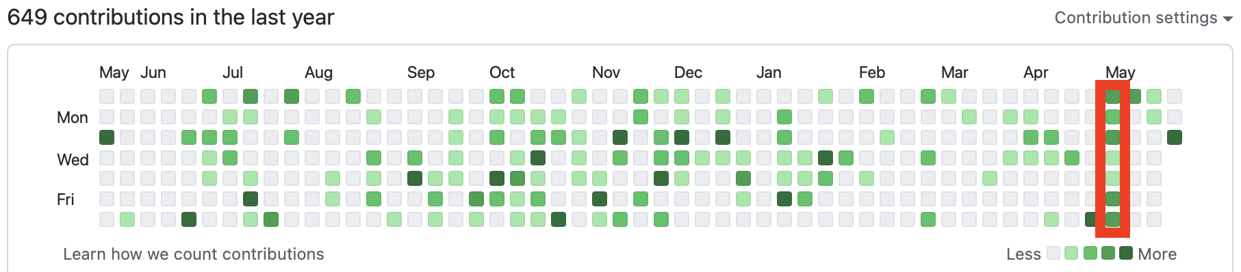
The above shows my Github contribution graph, with my vacation week highlighted in red. You can see that, while I did something every day, there was definitely a lot more activity at the weekends due to me taking time in the week to do other things. The busiest day was actually the Saturday (which falls outside the red box, to the bottom-left, due to the way weeks are shown here from Sunday – Saturday).

Was I happy with how it went? You bet I was! I hit my goal of writing a new assembler for the JVM, got to use a bunch of technologies I wanted to upskill on, and even hit one of my stretch goals. All-in-all, I’m calling the week a success 🎉

The Future

Availability

Due to time constraints, I didn’t make the projects available on Maven Central or the Gradle plugin repository immediately.

However, I had a bit of time this past weekend to come back to it and tidy things up, so Jasm is now available on Maven central. To use it in Gradle, you can just do

dependencies {
    implementation("com.roscopeco.jasm:jasm:0.1")
}

You can also download the first public release as a zip or a tarball, including the scripts that wrap running Jasm from the command line, from the Releases page on Github.

The Gradle plugin is currently awaiting approval for the Gradle plugin repository, but in the meantime you can grab the code and do:

./gradlew publishToMavenLocal

if you want to play around with it (but note, you’ll need to configure your gradle build to take account of your local Maven repo – which you can do by adding the following to settings.gradle.kts (not build.gradle.kts):

pluginManagement {
     repositories {
         mavenLocal()
         gradlePluginPortal()
     }
}

There is an example project here that shows how you might set this up, but the documentation is slightly outdated (and will be updated if/when the Gradle plugin is approved for release).

Will I be maintaining this?

In short, yes. I’ve had a lot of fun with this project, but I’ve also found it to be useful for a variety of things already, so I’ll definitely be expanding it, developing it and maintaining it going forward.

As always, Jasm is open source (MIT license) and ideas, suggestions, help and (especially) pull requests are always welcome!

Getting the most out of 16KB ROM!

Lately I’ve been doing a lot of work on the rosco_m68k hardware, specifically on integrating the new Yamaha V9958 video board. As part of this, I wanted to extend the firmware to support basic “virtual consoles”, so that if a V9958 is detected it will use that for text output, or fall back to the UART if there isn’t a video card.

I’ve written up a longish post on Hackaday with the implementation details of the console itself (it’s worth a read if you’re interested in implementing a scrolling 80×24 text mode console on a thirty-year-old graphics chip), so I won’t go into too much detail here about how it works – I’ll just prove it does work with a picture:

V9958 text mode console in firmware, running Jeff Tranter’s Adventure game

One of the problems I faced while putting this together was that the ROMs I used for the rosco_m68k are only 16KB in size, and while the community has already come up with a workaround for this (thanks to RTS4E75!), I wanted the standard firmware to work on unmodified boards, so it had to fit in 16KB.

I also didn’t want to sacrifice any of the existing features supported by the firmware (because backward-compatibility matters, even in retro single-board computers!), so I was left with a bit of a dilemma – how to fit the video driver and associated text-mode font into the few bytes that I had left after the Kermit loader, Easy68k compatibility layer and basic machine initialisation code?

After playing around with a few different ideas, I eventually decided I would split the ROM in two stages – Stage 1 would contain the bootstrap code, and everything that needed to stay resident in ROM. Stage 2 would contain the program loader (so Kermit currently, though that can now easily be swapped out for something else such as the experimental SD card support we’ve been working on).

How does this split save space? Simple – Stage 2 would be compressed, and Stage 1 would be in charge of decompressing it from ROM into RAM and running it from there!

I’m not going to lie, I’m pretty pleased with this. I seriously doubt I’m the first to do it, but being able to take an almost-full ROM and fit in an entire graphics driver and text font, plus a simple Zip-like decompression algorithm (I didn’t write this, I used the excellent liblzg code – a LZ compress/decompress with a decompression written in M68k assembly) is, I think, something of a win. Making it all work together properly (especially tying up the parts in stage 2 that needed to call back to bits in stage 1) took a bit of work, but once I’d ironed out all the bugs and made sure I wasn’t doing anything silly (like overwriting the loader code with the bytes it was loading…) it all works really well.

As always, the code is on Github.

PCB Fab Reviews – PCBWay

Full Disclosure: For the purposes of this post, PCBWay supplied me with a few free prototype PCBs, so I guess you could say that this is a sponsored post. Nobody gets a free pass around here though – I’ll be keeping this review totally impartial!

Hope they don’t mind me using this logo I screen-grabbed from their website…

By this point, I’ve had quite a lot of PCBs made out in China, with varying results, and I have a “go-to” manufacturer whose work I’m generally very happy with. I’ll refer to that manufacturer as Brand X in this post.

I’m always on the lookout for new and better things though, so when PCBWay got in touch recently to a) compliment me on my project, and b) offer me free PCBs in return for a review (this review, in fact) I was more than happy to accept. And not just because of the compliments (though flattery does go a long way) – I was genuinely interested to see how they stacked up against the producers I was more familiar with.

So here’s what I did – I sneakily had them make a board that I’d already (recently) had made by Brand X. I figured that way, I could do a side by side comparison and tell you about it. Sound good? Let’s get to it!


The Board

For the purposes of this, the board I ordered was the rosco_m68k bus board prototype (revision 0). This board is a local-bus backplane for my rosco_m68k Motorola 68010 project.

The finished board (PCBWay version) demonstrating why I’m not a professional photographer

Technically, this isn’t a hugely challenging board from a manufacturing perspective. It’s a two-layer design, although the front layer is just one big copper pour, with all the routing happening on the bottom. The smallest trace width on here is 0.160mm (6.3mils) with clearances being the same. Everything is through-hole – there’s no SMT pads on here, no vias and no thermal reliefs or anything like that. In short, it’s a very simple board that should be well within the capabilities of any fab, and shouldn’t break the bank. Ideal for a side-by-side comparison.

The board itself is 160 x 115 mm, and for the purposes of the review, I ordered with the same options from both manufacturers – FR4 in blue, lead-free HASL, 1.6mm thickness and 1oz copper.


Comparison 1 – Order Process

Ordering PCBs is by this point second nature to me, and to be honest there wasn’t a lot to choose between PCBWay and Brand X in this regard. Both websites just worked and ordering was a breeze – Upload a zip with gerbers and drills, get instant quote, set options and click Order.

The approval process did take slightly longer with PCBWay, but then this was my first order with them so I guess they check things a little more carefully. In any event both companies had passed my order to production within a day or so, so no big deal.

Winner: Tie


Comparison 2 – Price

I knew Brand X would be hard to beat in this category as they’re widely considered to be the cheapest around. And, pound for pound (well, dollar for dollar, but whatever), I was right. Here’s how the pricing stacked up for 5-off:

BrandBoardsShippingTotal
PCBWay$47$28$75
Brand X$17.50$38$55.50

PCBWay’s shipping was a fair bit cheaper than Brand X‘s, but the board price is considerably cheaper. Cheaper doesn’t always (or even usually) mean better of course, but this category is about raw price, and we have a clear winner.

Winner: Brand X


Comparison 3 – Lead Time

I ordered from Brand X on the 26th April, with the PCBWay order being made the next day, 27th April. I was interested to see how shipping time stacked up on this board as it’s a bit of an odd size, and blue (both of these can have impact on manufacturing time).

Despite the one-day lead Brand X had, both boards were actually handed to the carrier on the 29th April, so PCBWay are the clear winner here. Both were within the promised 2-3 day time, but PCBWay smashed it by almost an entire twenty-four hours.

Winner: PCBWay


Comparison 4 – Delivery Time

I didn’t think it was fair to compare delivery times for two reasons:

  • This isn’t a comparison of international logistics companies
  • International shipping is generally hosed at the moment due to Covid-19

For those reason, there’s no comparison in this category (suffice to say both took longer than they would have pre-Covid, with neither one markedly worse than the other).


Comparison 5 – First Impressions

First impressions of the boards were good – both boxes contained the ordered quantity, and the boards themselves looked good.

To me, the PCBWay boards beat Brand X boards though on purely aesthetic grounds – the blue was, well, just more blue. I was actually surprised by the difference, as I’d assumed that everyone would just use the same raw materials, but the deeper blue did look (to my eye) much nicer.

Brand X lighter blue, left, vs PCBWay deeper blue, right

A cursory inspection also showed some silkscreen issues on the Brand X boards that didn’t show up on the PCBWay ones. For example, Brand X‘s board:

I don’t know where these horizontal strike-throughs came from on Brand X‘s board

Vs PCBWay:

The printing appears perfect on the PCBWay board

You might argue that these differences are just cosmetic, but how a thing looks matters. When you’ve spent many hours designing a thing and it comes back from manufacturing not looking its best, the disappointment is real.

Winner: PCBWay


Comparison 6 – Assembly and operation

Another category where there’s no clear winner, which is to be expected really as this isn’t a challenging board to manufacture by modern standards. In fact, if either board had been difficult to solder or failed to work I’d have been amazed.

As it was, both Brand X and PCBWay’s boards were great to work with, a dream to solder (there were no problems with even the fiddly bits like the Micro USB socket) and worked perfectly. As one would expect.

Winner: Tie


Conclusion

Overall Winner: PCBWay

In this totally subjective test, PCBWay take the victory, if only by a nose. Are they the cheapest? Well, no. But as I said, cheaper isn’t always better, and when it comes to quality PCBWay definitely deliver the goods.

Is that worth the extra money? Only you can decide that. Personally, I’m looking forward to redoing this with a more challenging board and really putting them through their paces.

Will I use them for every board from now on? In all honesty, probably not. I have a lot of prototypes made that inevitably end up as scrap, and for those cost is the driving factor (given I can be assured they’ll function correctly, of course).

But will I use PCBWay again? Absolutely. Because most of the time, quality matters.

Also, their blue FR4 is, well, bluer. And I like that.


If you enjoyed this post or even found it useful, and you have PCBs to make, why not give PCBWay a try?

None of the links in this post are affiliate links, and other than the free boards that were supplied for review purposes I don’t receive anything in return for your attention or clicks.

Fake MC68010s Spotted

When you’re in the market for Motorola 68k CPUs (as I am), chances are at some point you’ll turn to eBay. And sure, there are plenty listed on there, with prices ranging from super-cheap to fairly-reasonable.

However, as always with eBay, caveat emptor is king! When you receive your chips, have a good look at them. They should look like this:

Click to enlarge

Notice that the Motorola logo looks good, the text is kinda small, and the date code makes sense (1992, week 51 in this case).

Now, check these out:

Click to enlarge

Notice here that the logo isn’t complete, the text is bigger than on the previous chip, and the date code suggests these were produced in the very first week of 2019 (or maybe 1919!?). I’m pretty sure Motorola weren’t producing these chips at that time…

You can’t see it too well in this picture, but the surface of the chip is sort-of rough, suggesting someone’s used some kind of tool to grind the part number off…

It turns out that these chips are either fakes, or re-badged original parts, and they’re not 68010s at all, but rather 68000s. If they’re fakes, they’re reasonably good ones – they work quite well as 68000s. Of course, the 68010 is pin-compatible with the 68000, so unless you have code that specifically uses the added features in the former, you might never know these aren’t the real deal.

I’m not sure why anyone is faking (or re-badging) these chips – given that these cost me a couple of dollars each I can’t really see where the margins are. I guess someone, somewhere has a bunch of 68000s, a facility for re-badging them, and the belief that they’ll sell much better if people think they’re buying a 68010. Who knows, maybe they’re right (I mean, I bought some, so… 🤷)

Now, I know that some people like to buy a 68010 as an “upgrade” for their old Amiga or ST (and maybe MegaDrive too, are people doing those?). It occurs to me that some of them might inadvertently purchased one of these imposters, and because the software on those machines isn’t generally written to take advantage of the 68010s features, they might not know it.

If you’ve upgraded your machine and your worried, and you have the facility to assemble some code, the following will let you know if you’re running on The Real Deal or one of these rebadged 68000s:

movec.l VBR,A0    ; Copy vector base register to A0...
movec.l A0,VBR    ; ... and load it back into VBR

If you’re running on a bona-fide 68010 (or above), this shouldn’t do anything. On the other hand, on a 68000 (even a cleverly-disguised one) this will cause an instant illegal instruction exception (vector 0x04). How your computer tells you about this will vary, but I’m guessing it’ll let you know…

rosco_m68k IO device – An Arduino Adventure

This weekend I’ve had a lot of fun playing with a proof-of-concept Arduino-based IO device for the rosco_m68k. Along the way I’ve learned quite a bit about the Arduino, identified a few future enhancements for the rosco_m68k design, and generally had a fun (if sometimes frustrating) time. It’s been a while since I’ve done any real hardware hacking on the rosco_m68k, so it’s been a nice change.

This post will probably run a bit longer than usual, so the TL;DR is that I wanted to prove that the expansion connector and bus layout of the rosco_m68k could be used to make new devices that would map into the computers IO space, and I (naively!) thought that an easy way to do this would be to use an Arduino hooked up to the computer’s bus. It (finally) works, but it wasn’t as easy as I’d hoped, and along the way I had to learn a bit more about the Arduino’s hardware while also becoming re-acquainted with the MC68010 and MC68901 user manuals and spend a lot of time looking at logic traces.

If you just want to skip to the end, the code is on GitHub.

Continue reading “rosco_m68k IO device – An Arduino Adventure”

rosco_m68k: PCBs Have Arrived!

An exciting day here – after several months of delays (firstly due to me procrastinating followed by production delays due to Coronavirus) the PCBs for my retro m68k computer have arrived!

Fresh off the plane!

I eventually decided to have these made by JLCPCB in China, and I have to say I’m very impressed with the quality and finish. On unpacking I immediately noticed a couple of things I didn’t spot before sending the gerbers off, but those are my mistakes – the fab is actually pretty much perfect. Drill is spot on and the silkscreen is lined up perfectly.

Obviously how satisfied I am may change once I get the components soldered on, but I’m pretty confident that the board will be absolutely fine. I’ll update here once I’ve done that.

Now, off to start soldering 🙂

rosco_m68k: August Update

Time for another update on the rosco_m68k, my homebrew retro computer project. As always, regular updates can be found on hackaday, so please do check there for the details (and like/follow if you want to!) – this will be more of a digest of what’s been going on over the past couple months.

The Headline

So I guess the headline thing that’s been happening recently is that I’ve started working toward having a PCB manufactured for this thing. I realised I needed to press on with this after I took the breadboard in to work for a geek-out session with some of my awesome colleagues, and had a totally nerve-wracking commute with the breadboard (it survived, save for one current-limiting resistor which developed a loose connection).

So I started work on reducing the component count (more on that later) and actually designing a PCB. It’s now pretty-much ready to go off to OSHPark for manufacture (Yes, I could get it cheaper but I like purple and, y’know, yield) and looks like this:

(The real one will be purple…)

So that’s the hot-of-the-press headline (I finished it today), and I’ll update more once the boards are made. In the meantime, if you want more details, follow the project on Hackaday for (usually) weekly updates.

Lowering the component count?

In the original design of this computer, I went for a full 7400-series TTL design for all of the glue logic, and that was cool. I learnt a lot about designing with discreet logic gates, was forced to really think about the way I wanted my circuit to work, came to understand propagation delay in a way I didn’t before, and bought a lot more breadboard. That last point is important – fifteen 7400-series chips, while cool, take up a lot of physical space. And PCB fabs charge by the square inch.

It had been pointed out to me before (thanks, Ken!) that I could do with a couple of programmable logic devices what I was previously doing with ~fifteen discreet logic ICs, so I decided (in the interests of staying sane and solvent) to investigate. After a good bit of reading and learning, I’ve now replaced most of the 7400-series on the board with two ATF16V8QL (link to PDF) CPLDs.

This is a win in more than one respect – not only has it saved me board space but it’s made routing the PCB much easier, cut down the current draw of the board, fixed up some propagation delay issues and allowed me to (finally) fix the bug with the expansion select line. These chips were available at the time the CPU I’m using was released, are still in production today, and cost me around £1 each (delivered, based on 5-off, from Farnell in the UK). They’ve taken over all address decoding and IO glue logic, and I highly recommend them.

What About Software?

Things haven’t stood still on the software front – since my last blog I’ve fully integrated the MC68901, gotten timers and interrupts working, and made the UART work such that the computer can now talk over serial (via a CP2102 Serial-to-USB converter I had lying around). Work on an OS for this thing continues apace, and it already has some basic memory management, a fully async serial driver, and has been demonstrated with some (very) basic multitasking. My immediate plan is to implement a way to load software via serial (Zmodem) in the immediate term to make it so that, as I continue to develop the kernel, I don’t have to physically pull the ROMs to reprogram them.

It’s Going Well, Then?

I like to think it is, yeah. I’m having tons of fun, and this thing is starting to look like a product. Once the PCBs are made and I’ve done some more on the software, I think this thing will be at a point where other people might want one. Obviously it’s a 16/32-bit computer in a 64-bit era, but I kinda feel like it might make a great starting point for people wanting to really get to grips with bare-metal, without all the lies abstractions that modern architectures force on them.

The PCB design gets me to a point where the core computer is done, and the expansion connector I put in means I can continue to develop new bits without worrying about disturbing the ever-so-fragile connections on the existing breadboard. This will mean graphics, networking, and who knows what else.

And even if it never goes anywhere beyond the three prototypes I’m going to be building soon, I’ve learnt a hell of a lot from this project, and continue to do so every time I work on it – and that’s really all that matters, right?

As always, the rosco_m68k is open hardware/open source. The complete set of design, documentation and code can be found on Githib at https://github.com/roscopeco/rosco_m68k.

Running Code and Talking to the Outside World

I’m still having a ton of fun with the rosco_m68k single board computer, and regularly writing project logs on Hackaday. If you’re interested, be sure to follow the project there as that’s where the regular updates happen, but here’s an in-brief update on what’s been happening.

Firstly, the board now has a lot more wires:

The ROM and RAM are both now hooked up to the buses, along with a MC68901 Multi-Function Peripheral that handles IO.

The system is successfully running code from the ROMs, and the RAM is working fine. I have code that does a full write/read test of the on-board RAM, and other code that just uses it and both are fine.

There’s some new glue logic to support the MC68901 (the top board in the picture) which has upped the chip-count a bit, and I’ve completely redone power distribution which was starting to get a bit shaky due to the way the project has grown.

Everything is connected together via the buses in the center of the picture, and the control bus has grown to accomodate all the CPU control lines and the address decoder outputs.

I’ve had a bit of a nightmare this weekend trying to get the MFP working properly (See this and this on Hackaday if you fancy a laugh) but it’s finally working, and I’m almost at the point of sending “Hello, World” to a serial terminal. After that, I’ll be off to the races with this project – debugging is so much easier when you can actually output stuff rather than just run logic traces.

That’s all for now – as I say if you want to know more be sure to like and follow on Hackaday!

Retro Computer Update

I’m writing regular logs on hackaday.io about the m68k-based retro computer I mentioned I was building a while back, but I thought I’d post a quick update here too. If you’re interested in the project, be sure to follow it on hackaday as that’s where the regular updates are going.

The main progress so far has been:

  • Get the CPU free-running
  • Decide on a memory layout, and design an address decoder to support that layout
  • Build the address decoder
  • Decide how I want to lay the buses out on the board for easier interconnection
  • Actually wire up the buses accordingly

I actually designed the address decoder a while ago, but gathering the parts and then wiring it up has taken some time – I finished it yesterday. Since then, I’ve been breaking out the CPU signals onto control, data and address buses, which I’m doing on an otherwise-bare breadboard in the middle of the main boards.

Right now, the rosco_m68k looks like this:

It’s still free-running at the moment (I’ve not wired the memory to the bus yet as you can see) but all the control pins I care about (basically everything except the legacy 6800 peripheral pins and the function code) are now on the control bus. The jumpers you can see there are configuring those control pins for free-run mode and will be replaced by connections to the RAM and ROM.

I did come across a couple of design errors while building the address decoder, some of which I fixed and others I’ve decided I can live with for now (e.g. an issue with the expansion select line I only discovered once I’d completely built the decoder and hooked up the LEDs at bottom left).

Anyway, that’s where it’s at right now. I expect that after another day’s wiring, it’ll be ready to run real code, and I can’t wait.

PJ5 TTL CPU

Blog about the TTL based CPU design we're making

Don Charisma

because anything is possible with Charisma

Tech Filled Fantasy

One stop shop for all your tech-filled pleasures!