This weekend I’ve had a lot of fun playing with a proof-of-concept Arduino-based IO device for the rosco_m68k. Along the way I’ve learned quite a bit about the Arduino, identified a few future enhancements for the rosco_m68k design, and generally had a fun (if sometimes frustrating) time. It’s been a while since I’ve done any real hardware hacking on the rosco_m68k, so it’s been a nice change.
This post will probably run a bit longer than usual, so the TL;DR is that I wanted to prove that the expansion connector and bus layout of the rosco_m68k could be used to make new devices that would map into the computers IO space, and I (naively!) thought that an easy way to do this would be to use an Arduino hooked up to the computer’s bus. It (finally) works, but it wasn’t as easy as I’d hoped, and along the way I had to learn a bit more about the Arduino’s hardware while also becoming re-acquainted with the MC68010 and MC68901 user manuals and spend a lot of time looking at logic traces.
If you just want to skip to the end, the code is on GitHub.
The Goal
When I set out, I wanted to prove to myself that one could build devices that would expand the rosco_m68k by hooking up to the bus, being mapped in IO space (0xF80000..0xFBFFFF) at even addresses (the MFP takes all the odd ones) and supporting byte-sized reads. Simple, right?
For this proof-of-concept, I’m not concerned about decoding the address bus to support mapping at specific addresses – just mapping into all of the even IO space is fine.
In a decision that would later come back to haunt me, I decided to do most of this in software and use an Arduino (specifically, a Mega 2560 I had lying around).
The Plan – Version 1.0
Initially, I naively decided that I would hook up the data bus to the Arduino on some conveniently-adjacent pins, feed in AS, UDS and IOSEL and have it manage DTACK to control the timing of the read cycle. Nice and simple, no need for speed – because it was in control of DTACK it could take things at it’s own pace and the CPU would just wait-state until it was ready.
This exposed a mistake in the rosco_m68k – specifically, DTACK is always driven by the glue logic. It shouldn’t be broken out to the expansion connector as it can’t be driven by external devices. In fact, I did design for this, and there’s a separate signal for DTACK during IO bus cycles that is designed to be driven by devices (all devices other than the selected device should put their IODTACK into hi-Z), and it’s that line that should be broken out to the expansion connector, not the CPU’s DTACK line. Oh well, no matter, we can easily work around that…
The Plan – Version 2.0
So, version 2.0 of The Plan is basically version 1.0, but driving IODTACK instead of DTACK.
I’d realised by this point that having AS, UDS and IOSEL fed separately to the Arduino wasn’t going to fly – getting the timing right of reading the three lines separately and taking control of the bus when appropriate was a nightmare given that the Arduino SDKs digitalRead and friends aren’t known for their speed. It did work, but it seemed to be unnecessarily complicated and I decided to throw a couple of 7400s onto a breadboard and generate a STROBE signal in hardware (details here).
With that, I set up an interrupt on the Arduino that would respond to CHANGE on the STROBE line and take control of the bus. In pseudocode, The Plan looks like this:
On FALLING edge of STROBE (CPU asserts AS, UDS and IOSEL select us):
  * Enable IODTACK as an output pin
  * Negate IODTACK
  * Enable the eight data bus pins as outputs
  * Set the data byte, pin-by-pin
  * Assert IODTACK

On RISING edge of STROBE (CPU de-asserts AS, UDS and IOSEL drop too):
  * Tristate the data bus
  * Tristate IODTACK
The Arduino can still take things at its own pace, and everything will be fine.
Except it wasn’t.
The first steps – just managing DTACK (well, IODTACK as previously discussed :D) and not touching the data bus were fine. But as soon as I touched the data bus, everything went awry and the rosco_m68k would either hit an illegal instruction, raise an address error, or occasionally (and comically) go off an do it’s own thing. Mostly the latter involved dumping garbage over the serial link, but one time the randomness aligned well enough that it made its own loop over the last println instruction and just kept printing out the same message over and over again.
(Aside: To be clear, the unlikeliness of his happening should not be underestimated and I must say I was impressed).
Some hours (I think I slept on it at this point) and lots of staring at logic traces later, I figured out what was going on. On to…
The First Realisation
By this point, I’d got the Arduino driving an extra line I called SIGNAL which gave me an easy way to see in the logic traces when it was actually driving the bus. The theory was simple – drive SIGNAL high when entering the interrupt handler, and drive it low again when leaving.
Here’s an example trace from around that time:

There’s lots going on in that trace, but let’s focus on the areas I’ve marked.
1 – Latency
There’s obviously a couple of microseconds of latency here between STROBE going low and the interrupt code running. In actual fact I’d already done some work here to bring this down – it had been around twice as long as this before. In any event, the latency shouldn’t matter (from a functional point of view, at least) – DTACK is pulled high anyway, so the CPU is waiting for us. And that’s true, but we’ll come back to this later…
2 – Acknowledgement
This is really the important bit in this trace. Once the ISR kicks in on the Arduino, it’s not long before DTACK is pulled low and the CPU responds by de-asserting AS (the code here isn’t doing anything with the data bus – I’m just testing the IODTACK handling at this point).
The thing to notice here is that, off the right of the trace, the ISR is still running (SIGNAL is still high) meaning the Arduino is still driving the bus (and asserting IODTACK) but the CPU is already onto the next bus cycle (as you can see by the continuing activity on AS).
But, what? It’s supposed to be waiting for us to de-assert DTACK, right?
Finally, we come to the title of this section. I realised that the problem was due to the way the glue logic in IC5 generates DTACK. Although our ISR is still running and holding IODTACK, as soon as the CPU stops asserting AS the address decoder stops asserting IOSEL, causing the glue logic to stop paying attention to it. It immediately reverts to the normal DTACK generation, which raises the line (as no memory selects are asserted), signalling the CPU that everything’s fine, and it should carry on.
Unfortunately that means that in the full version of the code the ISR is still busy driving the bus lines and doing its thing, oblivious to the fact that the world has moved on and now other chips are being asked to also drive the bus. Contention ensues, the CPU reads garbage for the next instruction, and everything goes wrong.
The Plan – Version 2.5
I played around with the CUPL code for the glue logic for a while, trying out various ways to change the way DTACK is driven by IC5, or have a way to tristate the DTACK pin in the PLD so the Arduino could drive DTACK directly.
After a few fruitless hours spent cursing the horror that is WinCUPL, I gave up. The ATF16V8BQL simply didn’t give me enough product terms on the individual pins OE to let me tristate DTACK during IOSEL for UDS only, and I couldn’t come up with a way to change the generation in any useful way without requiring circuit changes and a board respin. And in any event, this was only a problem for Arduino – if I had a hardware chip select then tristating the lines would be plenty fast enough for none of this matter.
So, onward to…
The Plan – Version 3
I decided I needed to make everything happen faster. First of all, lets look again at that latency.
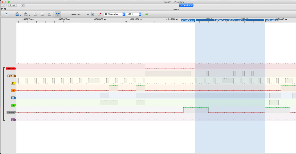
So, there are two things to notice here.
Firstly, the ISRs take too long to run. By this point, I’m driving the data bus as well as DTACK and have done a bit of optimisation, but the Arduino is still driving the bus long after the CPU has moved on. Again, we’ll come back to that.
Secondly, look at the latency between AS being de-asserted (the top line) and the ISR that responds to that kicking in (the second to last line) – it’s almost 4µs.
It’s not until that second ISR kicks in (driving SIGNAL high the second time) that the Arduino tristates the bus, so all that stuff going on in the meantime is happening during bus contention, meaning the CPU is reading garbage (by the time the second ISR runs, the CPU is already well into setting up for an Illegal Instruction exception).
So I figured that, given that changing pin states etc takes a bit of time on the Arduino, I could actually use that to my advantage and do everything in a single interrupt handler. Basically, if I set everything up, put the data on the bus, then immediately returned it to tri-state and did the IODTACK thing just right, then the timing would work out.
Here’s the first stab at that:
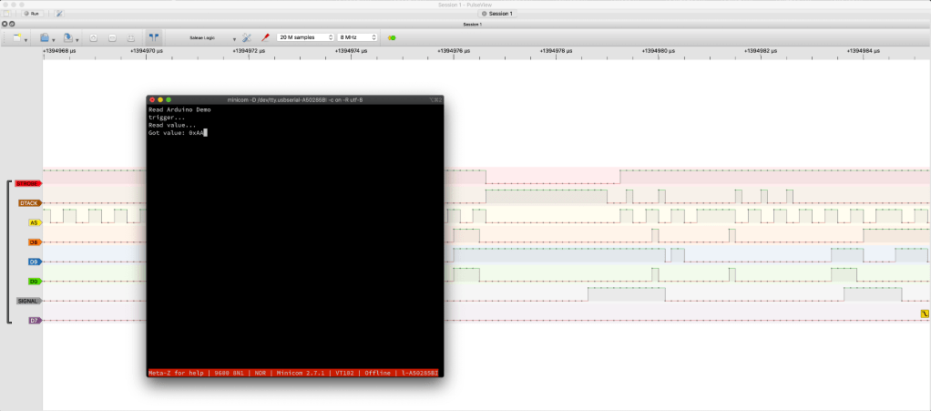
This image holds the first tantalising glimpse of light at the end of the tunnel – the minicom windows shows the correct value was read (0xAA).
Sadly, the machine still crashed, and looking at the trace it’s easy to see why – the ISR is still driving the bus for way too long. But it almost worked, and now I have something I can work with – I just need to optimise the code in the ISR!
(As an aside, the second ISR is still running in this trace, but now isn’t doing anything except driving the SIGNAL line. This will remain the case for the rest of the traces, as I’ve not gotten around to switching from the pin change interrupts I started with).
Optimising the ISR – The Plan 3.1
So I need to make the ISR run much more quickly. Ideally it needs to have the bus set up and everything done just after the CPU de-asserts AS. With some careful control of the timing of when it puts the data on the bus, and when it returns it to tristate, I can make this work.
I took a deep dive into the Arduino code, and ended up getting rid of almost all the code that used the SDK in favour of talking directly to the on-board MCU. I learned the following important lessons:
- digitalRead and digitalWrite are considerably slower than direct port access!
- I can shave a bit of time off the interrupt latency by doing my own interrupt handling, rather than relying on attachInterrupt. I’d already done this earlier, and could do more if I wanted to (I didn’t, not yet at least) by switching to naked ISRs.
- By being a bit more careful with pin choice for the various data bus lines I could save a bit of time by not having to do any bit manipulation of the ports, and could instead just blindly write to them (this saves a read of the port at the low level).
- As an extension of the previous point, writing all eight pins of the data bus could now be achieved with a single byte-sized register write, rather than setting the eight pins individually.
I spent more time with Atmel data sheets, and learned more about the Arduino’s low-level guts than I have in any other project I’ve done. The code I ended up with, which is kind of horrible, totally specific to the Arduino Mega, and does the job perfectly (possibly in spite of itself!) looks like this:
#include <Arduino.h>

// This is the byte that will be placed on the bus
#define DATA_BYTE           ((uint8_t)0xC0);

#define DATA_BUS_PORT       PORTA
#define DATA_BUS_DDR        DDRA

#define DTACK_PORT          PORTC
#define DTACK_DDR           DDRC

#define SIGNAL_PORT         PORTL
#define SIGNAL_DDR          DDRL

#define DDR_OUTPUT          0xFF
#define DDR_INPUT           0x0

#define IS_STROBED          PINE & 0x10 != 0

#define TRI_STATE_BUS                               \
    DATA_BUS_PORT = 0;                              \
    DATA_BUS_DDR = 0;

#define TRI_STATE_DTACK                             \
    DTACK_PORT = 0;                                 \
    DTACK_DDR = 0;

#define NEGATE_DTACK                                \
    DTACK_PORT = 0xFF;                              \
    DTACK_DDR = DDR_OUTPUT;

#define ASSERT_DTACK                                \
    DTACK_PORT = 0x0;                               \
    DTACK_DDR = DDR_OUTPUT;

#define SIGNAL_OUT          SIGNAL_DDR = DDR_OUTPUT
#define SIGNAL_HIGH         SIGNAL_PORT = 0xFF
#define SIGNAL_LOW          SIGNAL_PORT = 0x0

#define OUTPUT_BUS(data)                            \
    DATA_BUS_PORT = data;                           \
    DATA_BUS_DDR = DDR_OUTPUT;

ISR(PCINT0_vect) {
    if (IS_STROBED) {
        SIGNAL_HIGH;
        NEGATE_DTACK;
        OUTPUT_BUS(DATA_BYTE);
        ASSERT_DTACK;
        SIGNAL_LOW;
        TRI_STATE_BUS;
        TRI_STATE_DTACK;
    }
}

void setup() {
    TRI_STATE_BUS;
    TRI_STATE_DTACK;

    SIGNAL_OUT;
    SIGNAL_LOW;

    *digitalPinToPCMSK(11) |= bit (digitalPinToPCMSKbit(11));
    PCIFR  |= bit (digitalPinToPCICRbit(11));
    PCICR  |= bit (digitalPinToPCICRbit(11));

    Serial.begin(115200);
    Serial.println("Waiting for strobe...");
}
The key things to note here:
- I’m directly accessing ports for all pin access
- I’m still using pin change interrupts, even though I don’t technically need the second (rising) interrupt any more – but the timing works (and the second interrupt just does nothing)
- The code is still reasonably readable, though I’m using preprocessor macros rather than inline functions as I found it slightly faster.
- Using this with another Arduino device would be significantly harder than if it were written to the SDK API, but I don’t care about that…
- I set the SIGNAL line to low before tristating the bus – this is actually serving as the slight delay I need, which allows the CPU to latch the data.
With this, things are looking much better at the trace level:
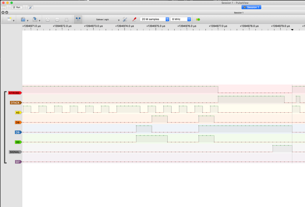
It’s All In The Timing
The previous trace shows the ISR finishing at roughly the same time as the CPU de-asserts AS (notwithstanding the resolution of my analyser, of course). It’s worth remembering however that I set the signal to low before I tristate the bus, so actually the cycle continues just slightly after the end of the bus cycle (it finishes during the period where AS is high prior to the next cycle).
For completeness (and because I feel better being in control of the timing directly) I modified the code, moving the SIGNAL line change to after everything else and doing the delay with a couple of nop instructions:
ISR(PCINT0_vect) {
    if (IS_STROBED) {
        SIGNAL_HIGH;
        NEGATE_DTACK;
        OUTPUT_BUS(DATA_BYTE);
        ASSERT_DTACK;

        /* Delay here to keep data on bus for the required time */
        __asm__ __volatile__ ("nop;");  /* Each nop adds 62.5ns on 16MHz Arduino */
        __asm__ __volatile__ ("nop;");

        TRI_STATE_BUS;
        TRI_STATE_DTACK;
        SIGNAL_LOW;
    }
}
In tests, this is working just fine. The traces show the ISR running for slightly longer than I’d like, but obviously it has to be borne in mind that that now includes the lowering of the signal line.
Conclusion
Phew, this was a long post – possibly my longest ever!
I’ve learned a lot about the low-level stuff on Arduino, especially the way it handles interrupts and direct access to ports, but obviously I’m still learning – the way I’ve done all this is probably not the best way! If you spot anything I’ve done wrong or missed, please do let me know in the comments and I’ll try to keep the post updated.
And finally, as always, I’ve learned (again) that there’s always more than one approach to any problem, and there’s usually another way around when you run into a limitation of a given piece of hardware. In this case, the limitation was in the DTACK generation and glue logic on the rosco_m68k, and it feels really good that I was able to work around it.
That said though, I did file an issue to fix it in the future 😉
